Recently I was working on understanding Microcontrollers and IOT based devices for Security Research purposes. So, I thought of building a small home automation system for practice. I am yet to complete this, but for startup i’ll be sharing how I used Raspberry Pi 2 and some other electrical components to control my room’s lighting in this post. Also, I will not be talking about Initial setup for Raspberry here, you may find various tutorials for that.
NOTE OF CAUTION
Before we proceed further I’d like to WARN you about the DANGER of experimenting with the “Mains Electricity”.If anything goes wrong the worst consequence may be death or atleast burning down your own house. So, please DO NOT ATTEMPT to do anything mentioned in this article if you don’t understand what you are doing or better take the help of some experienced electrician.
Lets get started.
Hardware Requirements:
- Raspberry Pi 2 (Any other model with 5V power output will work aswell)
- USB WiFi Dongle
- 8 Channel relay board
- Some Female- Female jumper Wires
- Bulb Holder + Home Electric Wires
Other Requirements:
- Basic Understanding of Python or any other language (I'll be using python)
- Basic Understanding of Linux systems
- Presence of Mind
First, connect to the RPi using ssh and install “apache” & “php5” :
1 2 | |
You’ll need to install python’s GPIO library to control Raspberry’s GPIO pins:
1
| |
Now, before moving ahead you’ll need to understand the electrical components we will be using:
1. Relay:
A relay is an electrical device which is generally used to control high voltages using very low voltage as an Input. This consists of a coil wrapped around a pole and a two small metal flaps(nodes) that are used to close the circuit. One of the node is fixed and other is movable. Whenever an electricity is passed through the coil, it creates a magnetic field and attracts the moving node towards the static node and the circuit gets completed. So, just by applying small voltage to power up the coil we can actually complete the circuit for the high voltage to travel. Also, as the static node is not physically connected to the coil there is very less chance that the Microcontroller powering the coil gets damaged if something goes wrong.
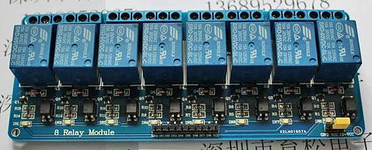
For the experiment, I am using an 8-Channel relay which can control 8 devices at a time. You may choose your own relay or relay board, but please make sure you read the maximum Amps@Voltage that the relay can work with to avoid any mishaps.
2. Jumper Wires:
Jumper wires are simple connecting wires that we will be using to connect Raspberry’s GPIO pins to the Relay.
3. Raspberry Pi 2:
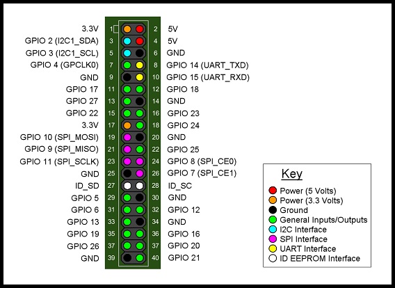
We will be using “Raspberry Pi 2"as a MicroController to control the relay. It has 40 GPIO(General Purpose Input Output) Pins. You can see the Layout diagram for these pins below. We’ll be using these pins to power up the relay and control the switching.
The Circuit:
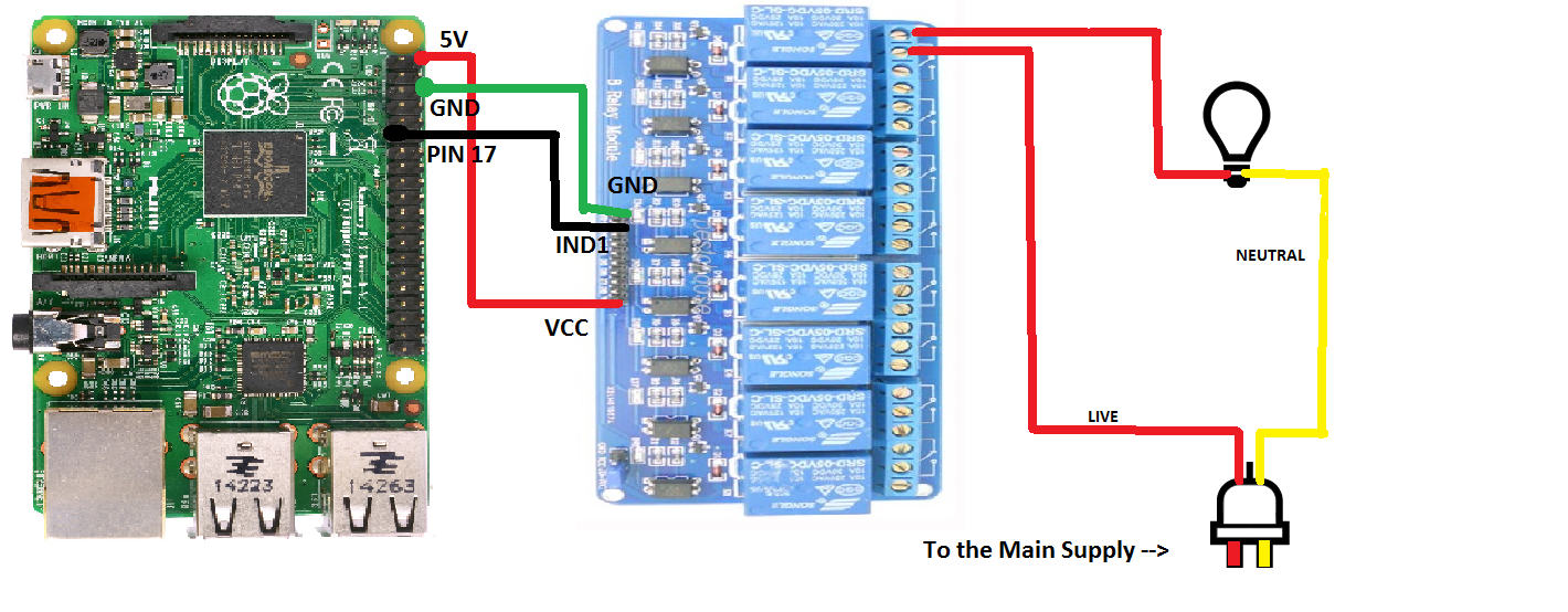
The Circuit is pretty simple. We will be connecting GPIO Pins to the Pins on Relay board. First connect the Ground (“GND”) Pin on Relay board to any Ground (“GND”) pin on the Pi. Then Connect the Input 1 (“IND1”) Pin of the relay to the GPIO PIN 17, we will be using the GPIO PIN 17 as an output to control First relay on relay bord. Finally, connect the “VCC” pin on relay board to the “5V” GPIO pin on Pi. To make this simple here’s the direct setup:1 2 3 4 | |
Now to the tricky part, We’ll connect the relay to the Bulb holder powered by Main Electric supply. But, first I want to give you a brief idea about how the lights are switched ON and OFF via direct power supply.
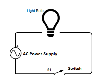
Now, when the light bulb is connected to the main supply, we usually do this by connecting two wires to the bulb. one of the wire is a “Neutral” wire and other one is the “Negative” wire which actually carries the current , also there is a switch added to the whole circuit to control the ON an OFF mechanism. So, when the swith is connected (Or Turned ON) the current flows through bulb and the neutral wire, completing the circuit. This turns the light bulb ON. When the switch is turned of, it breaks the circuit and the light bulb turns OFF. Here’s a small circuit diagram to explain this:
Now, for our experiment, we’ll need to make the “Negative Wire” pass through our relay to break the circuit and control the power flow using relay’s switching. So, when the relay will turn ON, it should complete the circuit and the Light bulb should turn ON and vice-versa. Refer to the below diagram for Full circuit.
Scripts for Controlling
Now, for the software part, I coded a simple python script to turn the relays ON/OFF using GPIO PIN 17 and a PHP code to run the python script usring any mobile device. You can find the codes below and on my Github (with CSS) - RPi_LightControl_demo aswell.
1
2
3
4
5
6
7
8
9
10
11
12
13
14
15
#!/usr/bin/python
import sys
import RPi.GPIO as GPIO
GPIO.setwarnings(False)
GPIO.setmode(GPIO.BCM)
args = sys.argv
pin = 17 # GPIO PIN 17
ctl = args[1] #Argument 1 for ON/OFF
if (int(ctl) == 1):
GPIO.setup(pin, GPIO.OUT)
GPIO.output(pin,GPIO.HIGH)
if (int(ctl) == 0):
GPIO.setup(pin, GPIO.OUT)
GPIO.output(pin, GPIO.LOW)
1
2
3
4
5
6
7
8
9
10
11
12
13
14
15
16
17
18
19
20
21
22
23
24
25
26
27
<?php

$ctl = $_POST['ctl'];
$command = "sudo python lights.py $ctl";
$result = shell_exec($command);
echo($result);

?>
<html>
<head>
<link href="style.css" rel="stylesheet" type="text/css">
</head>
<title>SaMaN's Room Control System</title>
<body><p class="head">Welcome to SaMaN's Room Control system!</p>
<form action="" method="POST" name="form">
<p class="title"> Control the lights from here: </p>
<p class="form">
<input type="submit" id="on" value="ON">
<input type="hidden" name="ctl" value="1">
</form></p>
<form action="" method="POST" name="form">
<p class="lol">
<input type="submit" id="off" value="OFF">
<input type="hidden" name="ctl" value="0">
</form>
</p>
</body></html>
NOTE = You’ll also need to add “www-data” user to sudoers file.
Note += The PHP code is only for testing purposes, it is advised not to host this on any public address :)
I’ll be completing this setup soon and hopefully come back with a new post on this. Till that time try this out, but with Caution.
P.S : I’m not really experienced with electronics, so it would be great to know if I’ve missed something or did something wrong on the electronics part.Please share your views in the comments :)
Demo Video 1 :
Demo Video 2 :
References